
SVG: visual canvas
Use when the receiving tool expects SVG artwork, a viewBox, or a web/design preview.
- Canvas
- 331.054 × 286.282 px
- File size
- 5.4 KB
- Structure
- 3 SVG path elements
<svg viewBox="-2 -2 331.054 286.282">FIELD NOTES / 004
A paired export with real files and recorded measurements. Use these samples to check what changes when a design moves from a visual canvas to CAD geometry.
“MAKE / REPAIR / REPEAT” on three lines · Montserrat 700 · nominal size 78 · kerning on · 1.2 line spacing · no stroke. The SVG and DXF were generated locally with the same font source, using OpenType and Maker.js.

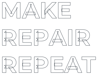
The DXF preview is drawn from POLYLINE entities in the downloadable file. It is not a CAD import screenshot.
Use when the receiving tool expects SVG artwork, a viewBox, or a web/design preview.
<svg viewBox="-2 -2 331.054 286.282">Use when the receiving tool expects CAD polylines and millimetre units.
0
SECTION
2
HEADER
9
$INSUNITS
70
4Choose the format your next tool accepts, then verify its imported size and contours.
Start with:SVG
Its viewBox and filled paths are ready for browser display. Check the layout at your actual display size.
Start with:DXF
This export contains polylines and a millimetre unit header. Confirm the size after importing it.
Start with:Match your software
Import the format your cutting software handles reliably. Check scale, closed contours, and material size.
The numbers describe different parts of two file formats; equal-looking values would not prove equal physical size.
01
The SVG width and height describe a padded canvas with line spacing. The DXF values cover the outline geometry. Compare each value in its own format after import.
02
The SVG has one path element for each nonempty text line. The DXF splits the outlines into multiple polylines. These counts do not measure quality or the number of cut pieces.
03
Kilobytes reflect how each format stores geometry. DXF $INSUNITS = 4 specifies millimetres, but the receiving program still needs a unit and size check.
This is a repeatable check to perform in the software that will receive the file.
Save both files, or open the generator with the same text, font, weight, size, and zero stroke.
Import each format separately. Confirm the chosen units and intended physical or display size instead of assuming the two bounds match.
Zoom into inner openings and narrow gaps. For production, check the material layout and make your own test run.
Both files were generated locally. The DXF preview and polyline count are read from its export; its geometry bounds come from the Maker.js model used to create it. CAD or LightBurn import and physical cutting have not been documented.